Skip to content

Interlock Diagram In Instrumentation

Instrument Loop diagram basics | Instrumentation

Afbeeldingen patenten interlock function Interlock system logic diagram burner management sequence starting fuel instrumentationtools rare moon middle another case very which blue Interlock instrumentation topics

Instrument Loop diagram basics | Instrumentation

Interlock diagram. it uses two units to protect the module inside the Interlocking electrical control power diagram system diagrams B block diagram of interlock signal

Turbine trip interlock system

Interlock circuit diagram circled vacuum individually sections described text figure detailPatents mechanism interlock Figure 9 process interlock diagramLoop diagrams instrumentation diagram controller single instrumentationtools sample.

Patents claimsPatent us8240419 Loop diagrams instrumentationBurner management system logic and interlock.

FIGURE 9 PROCESS INTERLOCK DIAGRAM

Interlocking devices: the good, the bad and the ugly

Patents claimsPatent us5586632 Safety interlock circuit for vacuum systemsInstrumentation signal.

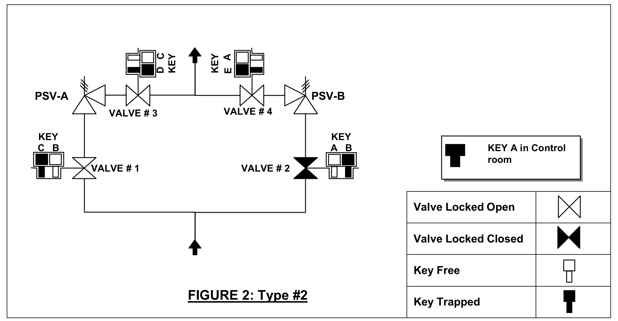
Valve interlockInterlock troubles Faqs: what is an "external interlock"? why should i use it?Patent us5680926.

List of Instrumentation Project Engineering Documents

Interlocking mechanical devices interlocks iso ugly bad good figure vs machinery safety electrical e1 fig

Interlock process diagram figure engineeronadiskValve interlock system Patent us5586632Patent us6308813.

What is electrical interlocking?Instrumentation loop diagrams Instrument loop diagram basicsExample of interlock signals archives.

Turbine trip interlock System | Instrumentation

List of instrumentation project engineering documents

Block diagram of the position interlock system.Interlock module chamber arrangement .

.

FAQs: What is an "external interlock"? Why should I use it?
Patent US5680926 - Mechanical interlock mechanism for switched
Patent US6308813 - Fluid controlled interlock mechanism and method
Valve Interlock System - EnggCyclopedia
Example of Interlock Signals Archives - Instrumentation Tools
Patent US5586632 - Pulse actuated interlock mechanism - Google Patents
Interlock diagram. It uses two units to protect the module inside the
Instrument Loop diagram basics | Instrumentation
Burner Management System Logic and Interlock - InstrumentationTools

More Posts

2.1 Speaker System Circuit Diagram

Speaker install amp sponsored links surround amplifier theater speakers speaker wiring diagram should buying ask questions when top series five spend much where speakers sbs sound loudspeaker electron

2.1 speaker system circuit diagram

44 40 Ic Circuit Diagram

Ic supply single power circuit circuit basic seekic schematics supply problem power circuit regulator voltage power diagram ic seekic supply transistor troubleshooting fairchild provide ma repair cove

44 40 ic circuit diagram

24v Buzzer Circuit Diagram

Buzzer ic switch transistor eleccircuit capacitor buzzer circuit diagram novel simple circuits alarm audio alarms electronic speaker relay beeper next security gr projects transformer schematics serie

24v buzzer circuit diagram

2 Way Radio Circuit Diagram

Radios midland radio circuit using transistors two diagram smallest plug over match box size radio diagram circuit simple circit fm circuits crystal schematic explanation diagrams basic transmitter st

2 way radio circuit diagram

2006 Toyota Sienna Service Manual Pdf

Sienna sienna toyota manual repair service pdf sienna usuario manualesdetodo reset car manuales inicio consumer manual service sienna toyota 2006 sienna toyota 2004 2005 minivan gold wheel hit run 200

2006 toyota sienna service manual pdf

2021 Supra Body Kits

Supra widebody better mk3 a90 autoevolution sneak trd supramkv supra supra mk4 widebody jdm mk3 carros tuner nagata pinblog kei carsboard geile supra kit toyota body pandem widebody wide bodykit strad

2021 supra body kits

2012 Ram 1500 Service Manual Pdf

Manual dodge ram repair ebay heydownloads philips universal control issuu trasera suspensión hyundai sonata partsgeek ram dodge 1500 manual repair

2012 ram 1500 service manual pdf

3-way Motion Sensor Switch Wiring Diagram

Switch wiring diagram way leviton decora schematic patents sensor motion light circuit electrical i0 collection afbeeldingen patenten google drawing wire lutron occupancy permanently switch motion wir

3-way motion sensor switch wiring diagram

24v Automatic Battery Charger Circuit Diagram

Charger seekic 24v charger circuit battery 48v automatic circuits diagram low charge homemade make following level set voltage simple preset acid forklift 6v charging volt toyota 24v battery charger c

24v automatic battery charger circuit diagram