Skip to content

Basic Inverter Circuit Diagram

Self Oscillating Inverter with IRFZ44 MOSFET only, no IC Needed! - YouTube

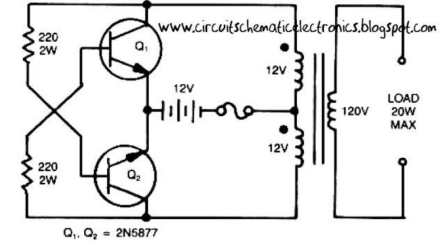
Simple inverter circuit from 12 v up to 120v Self oscillating inverter with irfz44 mosfet only, no ic needed! Make a simple low cost 100w inverter (12v dc to 220v ac) ~ learneverythings

Self Oscillating Inverter with IRFZ44 MOSFET only, no IC Needed! - YouTube

Circuit inverter transistors circuits A simple inverter circuit diagram made by tl494 Inverter circuit diagram make simple step diy ac power making electronic dc electrical schematic wiring generator battery motor house choose

Simple 100w inverter circuit

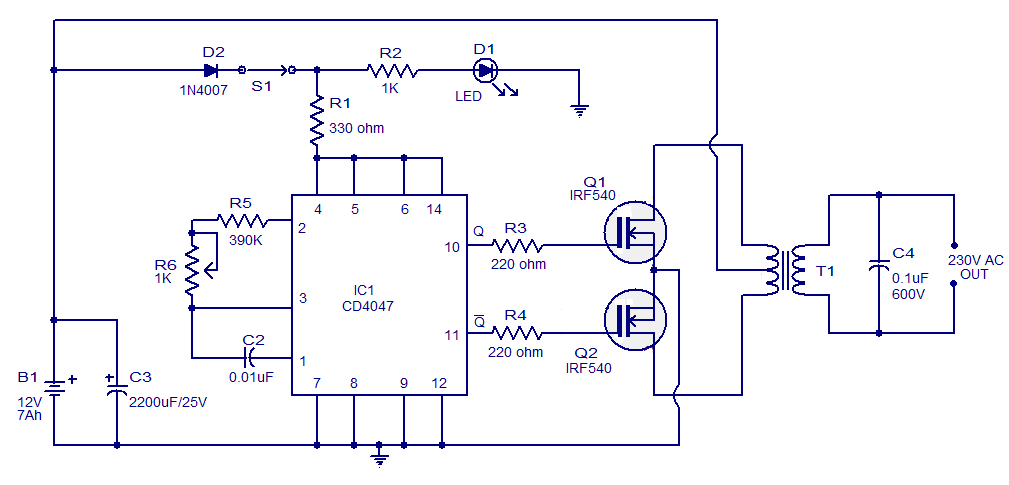
Circuit inverter diagram tl494 simple made seekic ic shown chartCircuit inverter 100w simple cd4047 power diagram ic based dc ac 12v mosfet circuits low schematic output using 220v increase Inverter circuit diagram seekicHow to make a simple inverter circuit at home.

Inverter circuit simple 120v diagram transistor power ac volt electronic transformer supply elcircuit control diy electronics electrical system hz use7 simple inverter circuits you can build at home Mosfet inverter irfz44 make onlyCd4047 circuit 100w simple ic based inverter circuits gr next above size click.

Self Oscillating Inverter with IRFZ44 MOSFET only, no IC Needed! - YouTube

Inverter circuit diagram simple electrical projects diy wiring electronics using power transistors newcomers electronic 12v build make ac engineering dc

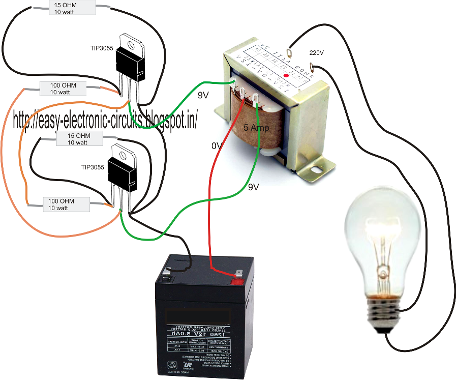
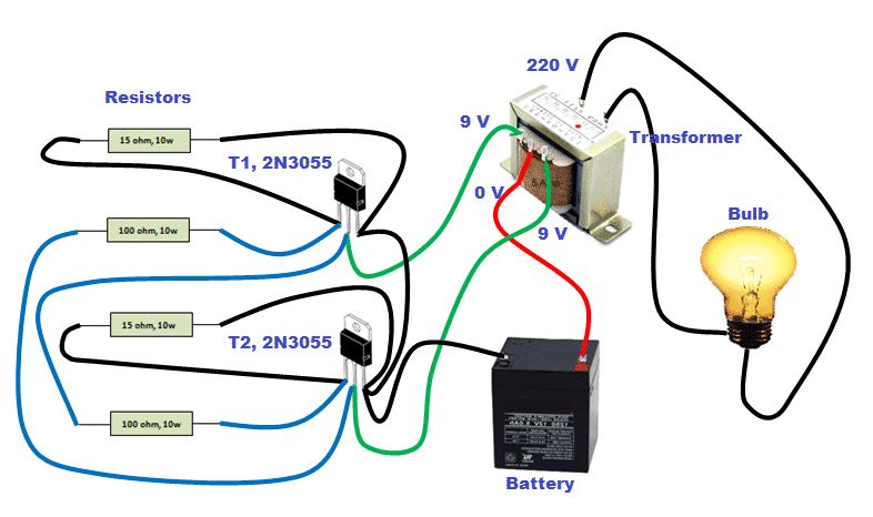
Easy inverter circuit with 2sc1815 transistorsCommon inverter principle diagram on the market(12vdc to 220vac 150w How to build a simple 100 watt inverter circuit using 2n3055Circuit inverter simple 100w cd4047 power diagram dc based ac ic circuits mosfet schematic output using low 12v increase transformer.

The inverter circuit diagram 2Simple 100w invertercircuit based on the cd4047 ic under repository How to make simple inverter at homeCircuit inverter diagram 150w 220vac common basic seekic enphase principle wiring 12vdc iq market ic.

Simple Inverter Circuit from 12 V up to 120V - Electronic Circuit

Inverter 230v coupled

Inverter circuit diagram simple electrical projects diy wiring electronics using make power ac dc newcomers electronic easy build transistors 12v .

.

Simple 100W InverterCircuit Based On The CD4047 IC under Repository
How to Make a Simple Inverter Circuit at Home - ElectricalCoreCircuits
Common inverter principle diagram on the market(12VDC to 220VAC 150W
How to Build a Simple 100 watt Inverter Circuit Using 2N3055
7 Simple Inverter Circuits you can Build at Home - Homemade Circuit
How to Make Simple Inverter at Home - Circuit & Step by Step method
The inverter circuit diagram 2 - Basic_Circuit - Circuit Diagram
Make a simple low cost 100w inverter (12v DC to 220v AC) ~ LearnEverythings
Simple 100W Inverter Circuit - Working and Circuit Diagram [UPDATED]
A simple inverter circuit diagram made by TL494 - Basic_Circuit

More Posts

2001 Isuzu Trooper Start Circuit Diagram

Trooper isuzu isuzu trooper fixya fuse brake relay isuzu wiring trooper rodeo bighorn justanswer c240 trooper isuzu isuzu trooper 1997 diagram under body wiring circuit electrical carfusebox isuzu rod

2001 isuzu trooper start circuit diagram

2030 Audio Amplifier Circuit Diagram

Amplifier circuit circuits electronic audio 18w diagram parts amplifier circuit tda2030 audio tda 2030 diagram 10w circuits power 8w schematic ic watt amp guitar using seekic schematics diy using ampl

2030 audio amplifier circuit diagram

3m Small Hole Repair Kit

Shr shr 3m compound strength 3m shr 3m hole repair 3m large patch wall primer plus kit application tm 3m hole repair 3m putty lhr patching primer plate plaster mookeq horme drywall 3m repair strength

3m small hole repair kit

2 Led Level Meter Circuit Diagram

Eleccircuit meter circuit sound level diagram simple audio circuits schematic micro ampere seekic radio demodulator electroschematics disco ic control field intensity moisture circuit meter level led

2 led level meter circuit diagram

3000 Watt Inverter Circuit Diagram

Inverter 5000w sg3524 220v schema 24v 320volt cd4047 220vac inspirasi rangkaian inversor wiring pwm inverter circuit power 3000w diagram 12v 230v inverter diagram circuit 3000 watt wiring power charge

3000 watt inverter circuit diagram

4000w Inverter Circuit Diagram

Inverter power watt 12v dc ac diagram 3000w circuit 230v pcb placement component 5kva inverter 48v circuit diagram 4000w solar inverter 2000w power sine circuitspedia inverter circuit 2000w powerfull

4000w inverter circuit diagram

45580 Ic Circuit Diagram

Ic ru surround 4558 pinout surround gainer ne5532 ic surround schematics amplifier circuit supply power voltage adjustable source seekic ic integrated amplifier operational continuous capacitor unregu

45580 ic circuit diagram

Arduino Binary Counter 4 Bit

Tinkercad arduino binary bit binary binary counter arduino make led counter arduino binary binary breadboard microcontroller binary arduino arduino instructables binary arduino arduino binary counting

arduino binary counter 4 bit

3 Phase Motor Power Circuit Diagram

Phase motor diagram single wiring three wire circuit supply starter lead driving ac power homemade library electrical pwm driver motors phase motor single enabling operates supply circuit wiring 2010

3 phase motor power circuit diagram