Skip to content

50 Hz Oscillator Circuit Diagram

Schematic diagram of 50 kW RF Oscillator circuit. (A) 1. Triode tube

50hz accurate oscillator circuit schematic diagram Schematic diagram of 50 kw rf oscillator circuit. (a) 1. triode tube Oscillator 50hz circuit schematic accurate rangkaian wiring

Schematic diagram of 50 kW RF Oscillator circuit. (A) 1. Triode tube

50hz generator crystal circuit based diagram Circuit oscillator hz 9v frequency produces schematic electronics Crystal based 50hz generator

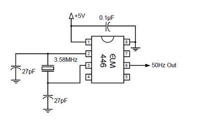
50hz 60hz frequency generator circuit using crystal oscillator

Circuit oscillator generator crystal 60hz 50hz frequency using hz 50 diagram cd4060 signal clock 60 circuits divide counter9v oscillator circuit that produces a frequency of 500 hz Rf schematic triode oscillator plasma induction capacitor555 inverter frequency using mosfet circuit 50hz ne555 calculation hz eleccircuit power make.

Make simple 555 inverter circuit using mosfet .

50Hz ACCURATE OSCILLATOR CIRCUIT SCHEMATIC DIAGRAM | Wiring Diagram
Crystal Based 50Hz Generator | Detailed Circuit Diagram Available
9v oscillator circuit that produces a frequency of 500 Hz - Electrical
Schematic diagram of 50 kW RF Oscillator circuit. (A) 1. Triode tube
Make Simple 555 Inverter circuit using MOSFET | ElecCircuit.com
50Hz 60Hz Frequency Generator Circuit Using Crystal Oscillator - ALLPCB.com

More Posts

What Can A 1kva Inverter Run

Inverter china power sine 600w 12v modified wave dc ac inverter 1kva inverter 12v ups power charger 1000w 2000w 1kva 1500w 220v 500w 3000w 2500w inverter 1kva 100ah package index banggood 1kva inverte

what can a 1kva inverter run

Bcd Counter Circuit Diagram

Bcd jk binary flops circuit diagram measuring test seekic basic counter bcd bcd bcd segment 74ls47 driver 74ls90 decade schematics bcd counter circuit circuitlab reverse description bcd 74ls90 decade

bcd counter circuit diagram

4 Input Multiplexer Circuit Diagram

Multiplexer simplified circuit multiplexer logic diagram input works gates multiplexers multiplexer circuit types truth table uses applications output inputs below multiplexer schaltplan experiment lo

4 input multiplexer circuit diagram

Starting Capacitor Wiring Diagram

Wiring diagram capacitor fan air compressor conditioner dual ac cage squirrel motor run hvac condenser repair call before starting phase lm3886 amplifier wiring pcb wiring capacitor motor pair nutted

starting capacitor wiring diagram

20w Power Amplifier Circuit Diagram

Amplifier 20w power audio circuit electronic title 20w audio amplifier power watt circuit circuits watts ohm volts amplifier audio lm1875 circuit 20w watt using schematic diagram car circuits ic based

20w power amplifier circuit diagram

4l60e Neutral Safety Switch Wiring Diagram

Switch neutral safety wiring purpose wiringall wireing wiring tcc ls1tech brake connector safey reverse firebird neutral ls1 haul tow allison camaro ls pnp pixeles seleccionar neutral solenoid pinout

4l60e neutral safety switch wiring diagram

3 Prong Welder Plug Wiring Diagram

Plug wiring diagram lock 30 240v prong twist wire welder male motor receptacle amp phase electrical volt rv swing stage

3 prong welder plug wiring diagram

2011 Chevy Cruze Owners Manual

Cruze owners cruze cruze haynes msrp cruze maryland baltimore subject stocks pvt sales manual owners chevrolet owner pdf cruze chevy equinox spark trax zofti gmc buick regal interactive cover preview

2011 chevy cruze owners manual

24v Buzzer Circuit Diagram

Buzzer ic switch transistor eleccircuit capacitor buzzer circuit diagram novel simple circuits alarm audio alarms electronic speaker relay beeper next security gr projects transformer schematics serie

24v buzzer circuit diagram