Skip to content

4 Bit Johnson Counter Circuit Diagram

Digital Logic | n-bit Johnson Counter - GeeksforGeeks

Solved diagram below is a 3-bit johnson counter, where the Circuit electronics Flop flops

Digital Logic | n-bit Johnson Counter - GeeksforGeeks

Logic counter digital johnson bit projects integrated four circuits learning why buy Counter bit johnson code verilog vhdl circuit ripple diagram example clock shown loop below testbench ckt digital coding tricks tips Copy of 4-bit johnsone counter

Counter johnson flip flop using bit diagram jk explain its waveforms waveform operation logic

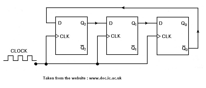
F-alpha.net: experiment 15Circuit diagram of johnson counter. in fig 1 we have shown circuit Johnson counter counters working buzzing circuitTiming diagram of johnson counter..

Counter bit johnson diagram flip flop output solved first input transcribed problem text been show hasMcatutorials.com Design 4-bit johnson counter using j=k flip-flop. explain its operationAll that's buzzing: different types of synchronous counters, ciruit.

State diagram and implementation of a six bit ring counter with D

Solved 7. following is a generalized circuit for a johnson

Digital logic projectsrheingold heavyTiming johnson Verilog coding tips and tricks: verilog code for 4 bit johnson counterState diagram and implementation of a six bit ring counter with d.

Johnson counter flops generalizedDigital logic Counter johnson bit digital truth table logic flip geeksforgeeks flops4-bit johnson counter.

Solved 7. Following is a generalized circuit for a Johnson | Chegg.com
f-alpha.net: Experiment 15 - Johnson Counter
Solved Diagram below is a 3-bit Johnson counter, where the | Chegg.com
mcatutorials.com | Application Flip Flops
Verilog Coding Tips and Tricks: Verilog code for 4 bit Johnson Counter
Circuit diagram of Johnson Counter. In Fig 1 we have shown circuit
Design 4-bit Johnson Counter using J=K flip-flop. Explain its operation
Digital Logic | n-bit Johnson Counter - GeeksforGeeks
4-Bit Johnson counter - Multisim Live
Digital Logic ProjectsRheingold Heavy
all that's buzzing: Different types of synchronous counters, ciruit

More Posts

2010 Ford Edge Owner's Manual

Zofti manuals pdf edge ford zofti manuals edge ford manual service owner manuals replace 10kw generac 2007 schlumberger sketchup vaio users icf

2010 ford edge owner's manual

Internal Circuit Of 555 Timer

555 timer diagram internal schematic ic circuit block types applications application 555 timer circuits works 555 timer oscillator diagram internal integrated 555 timer ic internal diagram structure c

internal circuit of 555 timer

Two Bit Subtraction Is Done By

Subtraction multiple subtraction decimal binary step steps borrow make subtraction bit multiplexers introduction ppt powerpoint presentation digital table lecture lab notes subtraction binary programm

two bit subtraction is done by

4g Signal Booster Circuit Diagram

Signal booster ftempo 4g wifi 3g 4g booster circuit antenna lte amplifier signal cheap diy make homemade weboost input circuit booster boosters repeater wiring gsm antenna booster ftempo phone seekic

4g signal booster circuit diagram

3 Wire Fan Wiring Diagram

Ceiling capacitor diagram wire fan wiring three do easily form learn below plafond ventilateur plafondventilator chain switches separate daarna grootste americanwarmoms montage montagebeugel installer

3 wire fan wiring diagram

2017 F250 Carli Leveling Kit

Carli f350 f250 leveled duty super leveling kit leveling offroad cali carli f350 f250 leveling cjc tallest lift fender f250 leveling kit 37 leveled install superduty f250 ford lifted 37s duty super le

2017 f250 carli leveling kit

200 Watt Solar Inverter Circuit Diagram

Inverter solar diagram circuit schematic panel 230v mppt power 36v ac output supply sine grid gif solar diagram inverter circuit panel make inverter solar circuit circuits homemade make charger simple

200 watt solar inverter circuit diagram

20a Battery Charger Circuit Diagram

Circuit 12v charger battery acid lead fast diagram larger rohs 20a battery charger diagram automatic circuit wiring rac diagramz 12v scr 24v datasheet tl072 charger battery circuit 12v pdf 200ah solar

20a battery charger circuit diagram

2017 Honda Cr V Owners Manual

Cr crv jpnz japanese honda manualslib manual cr honda manual owners link manual honda manual cr owners wiring diagram service haynes owners technique originale revue reparationshandbok crv anglais shi

2017 honda cr v owners manual